-


GNSS OEM Boards
-


GNSS Smart Antennas
-


GNSS Sensors
-


GNSS Reference Networks
-


Mobile Mapping System
-


PPP Service
-


Marine System
-


Total Station
-


Precision Agriculture
-


Controllers
-


GNSS Antennas
-


Tersus Software
-


Accessories
We have 2 different ranges of MVP products, MVP-XT32 and MVP-M2X.
The measurement range of MVP-XT32 is 120m, and the measurement range of MVP-M2X is 300m.
MVP-XT32 product support single(Last, Strongest, First) and dual returns.
MVP-M2X product support triple returns.
MVP-XT32: 640000 pts/sec(single return), 1280000pts/sec(dual returns).
MVP-M2X: 640000 pts/sec(single return), 1280000pts/sec(dual returns), 1920000pts/sec(triple return).
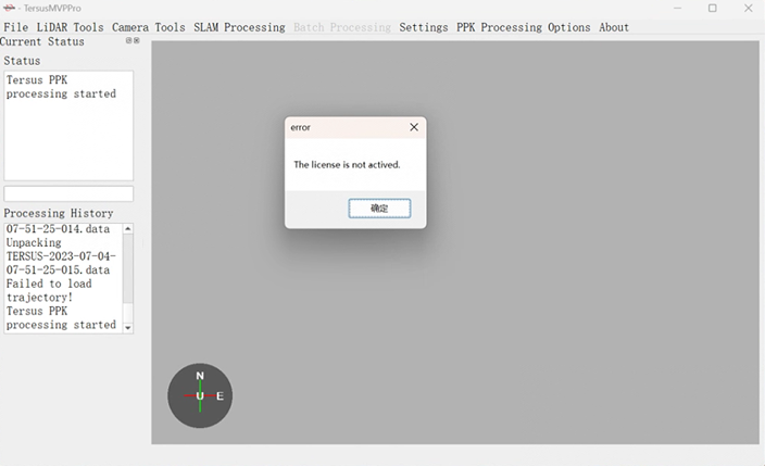
The most likely reason that this error is occurring is because your software’s license is not activated. TersusMVPPro should automatically pop up with the 'Tersus PPK License' to allow license activation if it finds one inactive. Once activated, The software will continue to enter the trajectory processing process, prompting the customer to select base data and configuration parameters.
If it does not pop up during processing, search for the 'TersusPPKMain.exe' on your computer to activate a license (default path: C:\TersusGNSS\TersusMVPPro\TersusPPKMain.exe).
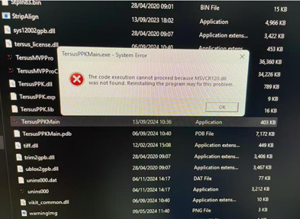
Generally, there will be no error message when opening the registration program. If a similar error message appears, it may be caused by missing MSVCR120.dll file in the computer system. You can try to copy this .dll file from another computer, this path: C:\Windows\System32 to the corresponding folder.
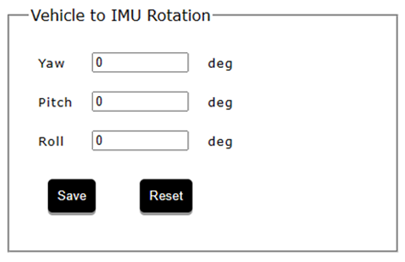
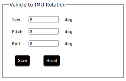
Before flying your MVP you should make sure that the 'Vehicle to IMU Rotation' window in the unit's GUI is configured correctly. To determine these offsets, compare the forward flying/moving direction with the forward direction of the payload. Below is the 'Vehicle to IMU Rotation' window; it can be found in the GUI-Settings-Geometry.
Below is the orientation reference of the MVP payload, this is used to determine the yaw pitch and roll offsets for the above window.
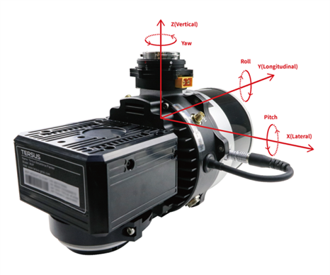
Note that the positive direction of the IMU's Y axis is from the IMU through the Lidar. Also note that the MVP is mounted along the Z axis. Most of the rotation offsets will therefore be in the Yaw offset.
Examples of determining the payload's orientation are below. Red is the direction of forward flight, blue are the IMU's axes.
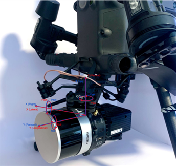
Example: Yaw 0, Pitch 0, Roll 0
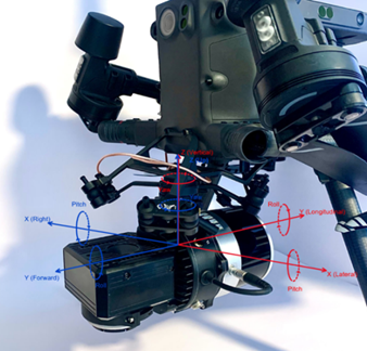
Example: Yaw 180, Pitch 0, Roll 0
If there is a data folder on your flash drive but no data (or not all of the data) is in the folder, the most likely cause is poor shutdown procedure. Another flight/drive is required to recover lost data.
When shutting down the MVP payload either on the GUI or with the power buttons, please make sure that you (1) stop the recording (either by pressing the power button once or by pressing 'Stop' on the GUI) and then (2) shut down the device (either by pressing and holding the power button for four seconds or by pressing 'Shutdown' on the GUI). DO NOT remove the MVP's flash drive before stopping recording (good practice is to leave it in until the unit is shutdown). Doing so can cause partial or complete data loss.
If there is only a data folder on your flash drive with data, however there is no TersusMVPPro project, the most likely cause is poor shutdown procedure. Unlike the previous case you may be able to salvage your data still (not 100% of the time)
In order to attempt to salvage your data, open TersusMVPPro using the application on your computer and select 'New Project' in the upper left corner of the window. Select ALL of the data files in the data folder. If your data is salvageable, TersusMVPPro will begin to process your data. Again, unfortunately this does not work 100% of the time and you may have to re-fly/re-drive to recover your lost data.
If you are flying at high altitudes with long stretches of no acceleration (straight line and constant velocity), you may notice that there is some drift in your heading data. In order to prevent this from occurring, try adding some dynamics into your flight. This could include changes in altitude, speed, or path. Introducing dynamics into the flight will help the IMU correct any heading drift.
This may be caused by a bug in the old firmware version; you can check whether the firmware version is the latest one. Contact the technical team for the latest firmware, and refer to chapter 5.3.5 of the MVP LiDAR Payload User Manual to learn how to update it.
Check whether the values of Vehicle to IMU rotation offsets in MVP GUI interface is correct before flight/drive.
If the above two possibilities have been ruled out by yourself, the issue may be related to the computer's graphics card. Please contact the technical team and describe the details of the problem for help.
If you have produced your colorized *.las file and it is completely black, you have done one of the following two things:
Left the camera lens cap on, and thus the camera took pictures of the inside of the lens cap (so nothing but black)
Not connected (or not correctly connected) the camera to the IMU
Neither of the above issues can be remedied in post processing, and so another flight/drive is required to recover the lost data. Below I will explain ways to prevent both from happening in the future.
For the lens cap, make it a habit to check that the camera lens cap is off of the device when you turn on the payload. You will already be near the device, and turning on the payload and taking the cap off of the camera will become habit in just a few flights/drives.
To ensure that your camera is connected, listen for two camera clicks when turning on your device, as well as a steady consistent click once you start recording. Additionally, if your camera and its serial number is visible in the GUI (under the Lidar on the Status page), your camera is correctly connected.
Remove the default path first under 'LiDAR Tools>Paths'. Then, select portions of the trajectory to be included in the final LAS by right-clicking on a part of the trajectory and selecting 'Start selection here' as shown in following figure. Selection ends are marked by white diamonds.
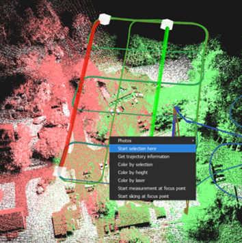
After you have selected the starting point for the desired path/trajectory selection, find the location on the trajectory for the desired end point of that path. Right-click this location and select 'Finish selection here'.
After finishing this step, TersusMVPPro will load and display the corresponding geo-referenced laser points of this selected path, continue colorizing and exporting.
When ≥2 paths on the interface and ≥2 paths are displayed in the 'LiDAR Tools>Paths' function list, the export will provide the 'export by path' option, and each path will export a *.las file.
When only 1 path is on the interface and displayed in the 'LiDAR Tools>Paths' function list, there is no path option for export, and the point cloud *.las file under the selected tractory is exported by default.
